

 English
 русский
 عربى
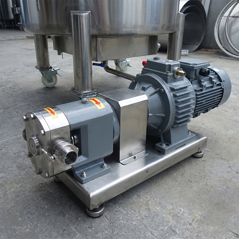
Static production lines often lack the flexibility needed for small-batch adjustments or additive dosing. Our Portable Sanitary Mixing Tank brings the mixing process directly to where it's needed. Fea...
READ MORE
Mixing Tank Design Guide: Sizing, Agitators, Jackets, Sanitary Details
Content
- 1 Fix the Duty Before Anyone Draws the Tank
- 2 Sizing: Volume, Fill Level and Headspace
- 3 Internals and Bottom Geometry
- 4 Matching the Impeller to the Fluid
- 5 Heat Transfer: Jackets, Coils and Temperature Approach
- 6 Materials, Finish and Cleanability
- 7 Drive, Seals and Control
- 8 Six Errors That Show Up After Startup
- 9 A Checklist to Approve Before Fabrication
A dairy processor once ordered a 3,000 L mixing tank, filled it to 2,600 L, and still waited 25 minutes for milk powder to dissolve. The tank was not too small. The agitator was. A single impeller sat 900 mm off the bottom on a fixed-speed drive, with no baffles, so the powder rode a slow surface vortex instead of being pulled down and wetted.
That case sums up the discipline: mixing tank design is a fluid problem first and a fabrication problem second. Two vessels with identical shells can behave completely differently once the impeller type, baffle set, fill level and jacket surface change. Work through the decisions in the order below and most surprises disappear before the drawings are released.
Fix the Duty Before Anyone Draws the Tank
Write the process data down before geometry. The five items below are the ones most often skipped, and they decide everything that follows.
The numbers worth locking in first
- Viscosity at process temperature, not at ambient, since a product reading 200 cP cold may fall to 20 cP at 60 °C.
- Solids content, particle size and the density gap between powder and liquid, which decide whether you need shear or plain flow.
- Minimum and maximum batch volume, because a tank sized for 5,000 L frequently mixes badly at 1,000 L.
- Blend time and homogeneity target, for example 95% uniformity within 10 minutes.
- Heat-up or cool-down rate, plus the cleaning method, since both change the internals.
It also helps to be precise about what a mixing tank actually does: the shell stores the product, while the impeller, baffles and bottom shape create the flow pattern that does the work. A tank specified only by volume is a container, not a mixer.
Sizing: Volume, Fill Level and Headspace
Total volume and working volume are different numbers, and confusing them is the most common sizing error. An agitated vessel normally runs at 70–80% of its total volume, with the remaining space reserved for foam, splashing and the spray ball.
| Parameter | Common range | What it changes |
|---|---|---|
| Working volume / total volume | 70–80% | Foam allowance, spray ball clearance, vortex control |
| Liquid height to tank diameter (Z/T) | 0.8–1.5 | Number of impellers needed on one shaft |
| Headspace above liquid | 15–25% of shell height | Foaming, splashing, CIP coverage |
| Baffle width | T/10 to T/12 | Breaks the vortex, converts swirl into top-to-bottom flow |
| Impeller diameter ratio, low viscosity | 0.30–0.50 of tank diameter | Flow rate versus shear at the blade tip |
| Impeller diameter ratio, high viscosity | 0.60–0.90 of tank diameter | Wall sweeping, heat transfer, dead zones |
Two practical rules follow from the table. A vessel with a liquid height above roughly 1.5 times its diameter usually needs two impellers on one shaft, and a tank that consistently runs below 40% of its working volume is a candidate for a smaller vessel or a side-entry agitator.
Internals and Bottom Geometry
Internals are inexpensive to add at the drawing stage and expensive to retrofit once the tank is piped in.
- Four baffles at 90 degrees, offset from the outlet, remain the default for low-viscosity duty; they convert swirling into top-to-bottom turnover.
- A dished bottom with a short cone drains better than a flat bottom and leaves less heel between batches.
- Use a flush, fully draining outlet at the lowest point rather than a raised dip pipe that traps product.
- Top-entry mounting suits vessels from roughly 1 to 30 m³, while side-entry agitators earn their place in tall tanks where shaft length becomes impractical.
Sensor pockets, sample valves and spare nozzles should be drawn now. Every one added later means another weld, another polish and another cleaning check.
Matching the Impeller to the Fluid
The core question is whether the process needs flow or shear. Low-viscosity liquids need bulk turnover, high-viscosity products need wall contact, and immiscible liquids or hard-to-wet powders need shear at the blade tip.
- Below about 100 cP: hydrofoil or pitched-blade impellers, sized for pumping rate rather than horsepower.
- 100–5,000 cP: pitched-blade turbines with a larger diameter-to-tank ratio, often in two stages.
- Above 5,000 cP: anchors, gates or helical ribbons running close to the wall, which also improve jacket heat transfer.
- Emulsion and dispersion duty: rotor-stator heads, sometimes operating under vacuum.
For simple low-viscosity blending, a single-wall agitated vessel is often the most economical answer, with the saved budget going into baffles and a correctly sized gearbox. A 500 L to 5,000 L SS304 blending tank covers a wide range of beverage, sauce and light chemical batches when the agitator is matched to the fluid.
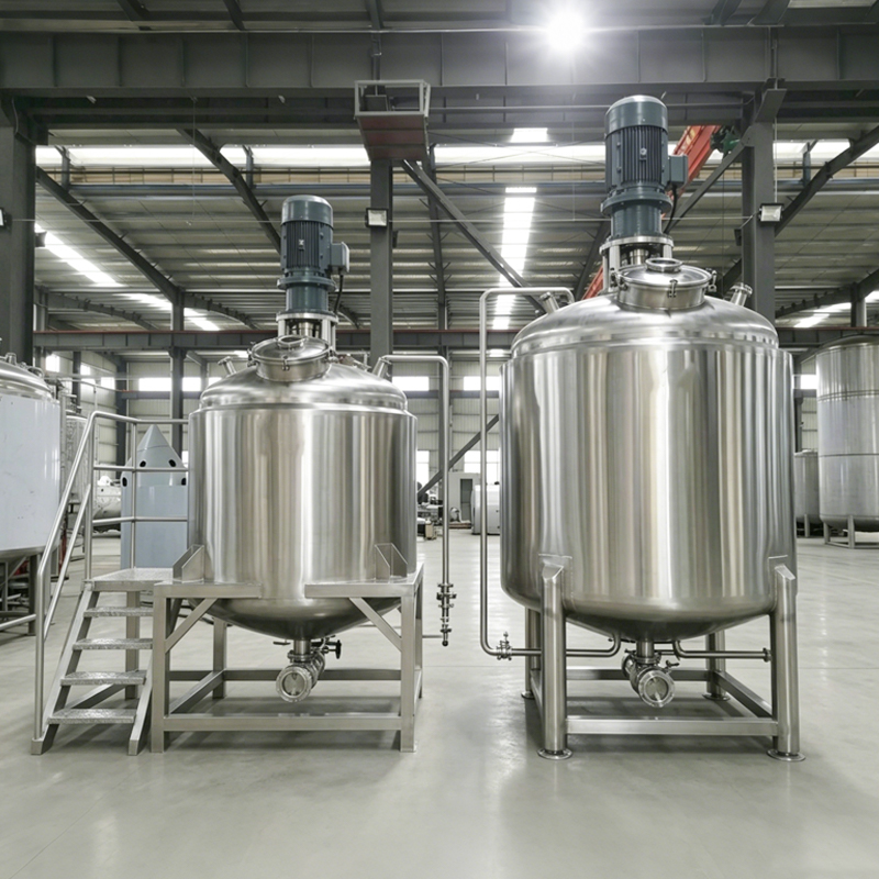 500L–5000L SS304 Single-Layer Blending Tank for DetergentsStainless steel mixing tank for low-viscosity detergent, beverage, and light chemical batches, with customizable paddle or anchor agitation and 500–5,000 L capacities.View Product →
When the process genuinely needs high shear
Rotor-stator heads turn at tip speeds of roughly 15–25 m/s and reduce droplets or agglomerates into the 2–50 µm range, which is why they are specified for emulsions, gums and pigment dispersions rather than bulk blending. They are not a cure for poor flow: a high-shear head inside an unbaffled tank still leaves dead zones in the corners.
 3000 RPM High Shear Emulsifying Tank with Rotor-Stator SystemHigh-shear rotor-stator homogenizer for stable emulsions, creams, and particle reduction, with SS316L contact parts and speeds up to 3,000 RPM.View Product →
Heat Transfer: Jackets, Coils and Temperature Approach
If the product must be heated or cooled, jacket area is frequently the limiting factor, because a control loop can only work with the surface area you build. Dimple jackets are the usual choice for vessels up to about 20 m³, half-pipe coils handle higher pressures, and internal coils add area at the cost of cleaning access.
- Match the media: steam for fast heat-up, hot water for gentle duty, glycol for cooling below ambient.
- Check the temperature approach, since a 10 °C approach needs far more area than a 40 °C one.
- Insulate the shell and jacket to reduce condensation and stabilise batch temperature.
A jacketed vessel with a dimple jacket and a variable-speed agitator handles both the blend and the temperature ramp in one unit, which removes a transfer step between vessels and the cleaning that comes with it.
 1000L Dimple Jacketed Thermal Mixing Vessel for Uniform HeatingDimple-jacketed vessel for syrups and chemical resins, using PLC temperature control, PT100 sensors, and rock wool insulation to reduce hot spots during heating.View Product →
Materials, Finish and Cleanability
Grade selection follows the product and the cleaning chemicals, not habit. SS304 covers most dairy, beverage and light chemical duty, while SS316L is the safer choice for chloride exposure, acidic products, high-purity work and longer service life.
- An internal finish of roughly Ra 0.4–0.8 µm suits most sanitary duty; pharmaceutical work often calls for mirror polishing.
- Slope the bottom toward the outlet and radius internal corners so product cannot pool.
- Verify spray ball coverage across the full working volume, including the upper shell and the underside of the top head.
- Eliminate dead legs on instrument nozzles, as they are a common source of repeat contamination findings.
Drive, Seals and Control
Specify torque and flow, not RPM. The gearbox should carry a service factor of at least 1.5 against the calculated mixing torque, because startup torque in a settled viscous batch can be several times the running figure. For sealing, a sanitary mechanical seal or a flushable lip seal keeps lubricant away from the product.
- A variable-frequency drive lets one tank serve several recipes and avoids overshearing shear-sensitive products.
- Load cells, a PT100 probe and a conductivity or pH sensor turn the vessel into a monitored process step.
- Recipe control on a PLC with data logging simplifies batch records and cleaning verification.
Six Errors That Show Up After Startup
- Sizing on total volume, then wondering why a half batch never blends.
- Omitting baffles on a low-viscosity product, so a surface vortex forms and powders float.
- Mounting the impeller too high off the bottom, leaving a sediment layer that never lifts.
- Undersizing jacket area, then trying to correct it with a larger control valve.
- Ignoring CIP coverage for the top head and nozzles.
- Buying on RPM instead of torque and flow, which appears later as motor overload in a cold, viscous batch.
A Checklist to Approve Before Fabrication
- Duty data: viscosity curve, solids, batch range, blend time target.
- Geometry: working volume, liquid height ratio, baffle size and count, impeller type, diameter and off-bottom distance.
- Heat transfer: jacket type, surface area, media, temperature approach, insulation.
- Materials and finish: grade, surface roughness, weld treatment, slope to drain.
- Drive and seals: torque, service factor, seal type, VFD range.
- Instrumentation and cleaning: sensor nozzles, spray devices, control philosophy.
Good mixing tank design is mostly a matter of order: fix the duty, size the geometry, choose the impeller for the fluid, then confirm the jacket, finish and drive can deliver what the process asked for. Get those four steps right and a 1,000 L vessel will behave exactly as predicted at 600 L, at 60 °C and on the tenth cleaning cycle.
YME Equipment Co., Ltd builds sanitary single-wall, jacketed, high-shear and vacuum mixing vessels for dairy, beverage, brewing, biotech and chemical duty. If you have duty data and a batch range, send them to the engineering team and have the agitator and jacket checked against the numbers before drawings are frozen.
News
-
-
For high-end personal care products, microbial growth in crevices and uneven surfactant distribution are critical quality risks. This Sanitary Single Wall Agitated Tank features a fully radiused inter...
READ MORE -
Yeast viability is the cornerstone of consistent fermentation, yet stored yeast often degrades due to temperature fluctuations and contamination. Our Sanitary Yeast Storage Tank provides a laboratory-...
READ MORE -
In large-scale operations, even minor surface imperfections can lead to "beer stone" buildup and microbial contamination over time. By utilizing SS316L stainless steel and an electro-polished interior...
READ MORE -
Air bubbles trapped in pharmaceutical ointments or cosmetic creams lead to oxidation and shortened shelf life. Our Aseptic Vacuum Mixing Tank solves this by processing materials under deep vacuum (-0....
READ MORE -
Small to medium-scale detergent producers often face the challenge of inconsistent batch mixing and inefficient material discharge in low-end vessels. Our 500L - 5000L SS304 Single Layer Blending Tank...
READ MORE
YME Equipment
-
Quick Links
Home Products About Solution Service News Contact -
Products Category
Mixing Tanks Storage Tanks Fermentation Tanks Brewing Equipment CIP Cleaning Systems Pasteurizers Beverage & Dairy Turnkey Solutions
-
-
Welcome To Visit Us
No. 15 Yinghua Road, Chengdong Industrial Park, Daxu Town, Xiangshan County, Ningbo City, Zhejiang Province, China -
Call Us
• Mob: +86 0574 6583 9268 -
Contact Us Online
• info@ymeequipment.com
Copyright © YME Equipment Co., Ltd. All Rights Reserved.
OEM/ODM Fluid Process Equipment Manufacturer
Brewery Equipment Supplier
